Fractal Terrain generation is the process to procedurally generate terrains like mountains, valleys, plains and more. It is a vast field with a lot of research on it. After seeing some work in the game Death Stranding 2: On the Beach with the beautiful landscapes, I decided to learn how to implement a terrain generator.
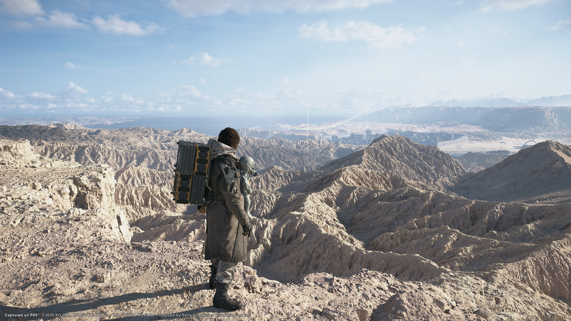
Death Stranding 2: One the Beach by Kojima Productions
So I started to research and decided to implement two algorithms: Fault Formation and Midpoint Displacement.
Heightmap
Before we generate the terrain, we first need a heightmap. A heightmap is a 2D raster image in which each pixel stores a numerical value, typically encoded as a grayscale intensity. By mapping these values to elevation, a heightmap can be used to reconstruct 3D geometry in the form of a terrain mesh. In our case, the terrain is represented as a rectangular 2D grid of polygons extending along the X and Z axes, with each point storing a height value along the Y axis. Thus, the heightmap determines the elevation of each point in the terrain, allowing the 2D grid to be transformed into a 3D surface.
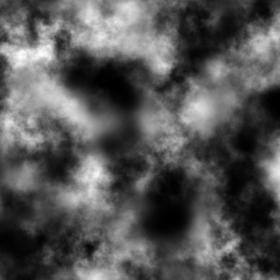
Raw 2D Heightmap, black values represent lower elevations and white values higher elevations.
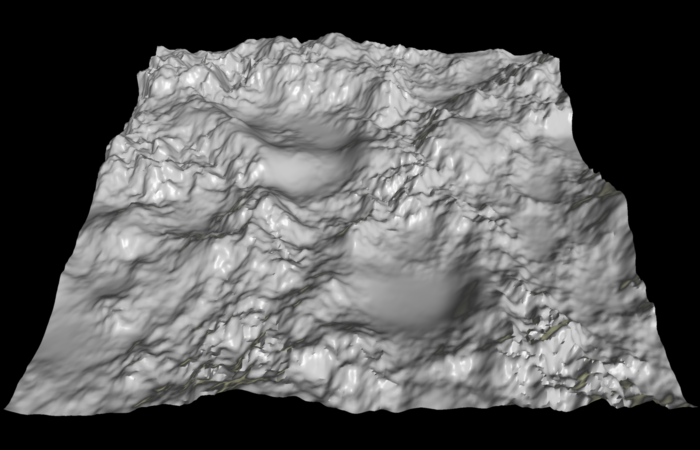
Heightmap to 3D Surface, mapping 0 to 1 values as low to high evelations.
I will use a struct to store the heightmap values and a float pointer to initialize and store the values:
struct Heightmap2d
{
public:
    Heightmap2d();
    ~Heightmap2d();
    //Functions...
private:
    int m_Width    = 0;
    int m_Depth    = 0;
    float* m_pData = nullptr;
};
Now to be able to generate our mountains and fields we need to model a class to abstract the Terrain. Terrain.hpp will do the job.
class Terrain
{
public:
    Terrain();
    ~Terrain();
    //Functions...
private:
    Mesh m_TerrainMesh;
    Heightmap2d m_HeightMap;
};
We will use this Base class to load heightmap values, apply filters and draw the terrain.
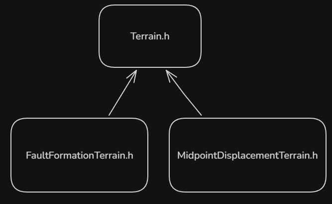
Terrain.h Base class
Fault Formation
Fault formation is the method of applying 'faults' to the terrain. We begin by creating a random line with points and , which have random values for X and Z. With these points, we create a line over the terrain heightmap and divide the grid into two parts. For one of the parts, we can reduce its height and maintain the height in the other. After that, we repeat this process times until a realistic terrain is formed.
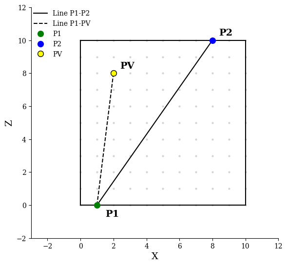
Line separation with and .
To apply the new height only on one side of the line we can do a simple cross product between the line and the line , with being the current point in the loop iterating over the grid.
if the result is < 0 raise the height of the point, else do nothing.
To implement this, we'll create a new class that inherits from our base Terrain. Here is the definition for Faultformation.h:
class FaultFormationTerrain : public Terrain
{
public:
    FaultFormationTerrain();
    ~FaultFormationTerrain();
    void CreateFaultFormationTerrain(float numOfIterations, float min, float max);

private:
    struct Line
    {
    public:
        glm::vec2 p1;
        glm::vec2 p2;

        void CreateLine(glm::vec2 a, glm::vec2 b)
        {
            p1 = a;
            p2 = b;
        }

    };

    Line GenerateRandomLine();
};
Each pass we change the height of the grid inside CreateFaultFormationTerrain() by using a simple linear interpolation equation where we gradually decrease the height of the mountains from maximum height to minimum height as the iteration increases.
float newHeight = maxHeight - ((maxHeight - minHeight) * i) / numOfIterations;Even after multiple passes the terrain looks visibly like a mountain but with sharp edges due to the nature of the algorithm.
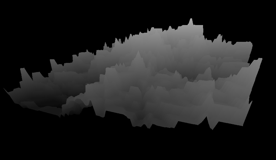
Terrain visibly unfiltered with sharp edges
To solve this we need to pass a filter to smooth the values so the terrain looks less "pointy" and to simulate terrain erosion. But before the filter we need to normalize all the values inside our heightmap to minimum and maximum height:
Filter
Literature suggests we use FIR (Finite Impulse Response). FIR is a low pass image filter and we will use to maintain low spatial frequencies and suppress the Heightmap high spatial frequencies, reducing the sudden edges of our mountains.
The formula transforms the points into with the formula:
where
- New value
- Filter value
- Last value
- Current value
After each filter pass we can see the changes being applied and the terrain getting smoother. The figure below shows a simple example.
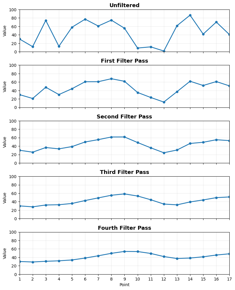
FIR Filter changes are visible after multiple iterations, smoothing the values
Given the formula we will write the needed functions in Terrain.h base class so that when a new algorithm uses the filter it can reuse the functions.
The function to apply the filter:
float Terrain::ApplyFIRFilter(int x, int z, float lastVal, float filter)
{
    float curVal = m_HeightMap.Get(x, z);
    float newVal = filter * lastVal + (1.0f - filter) * curVal;
    m_HeightMap.Set(newVal, x, z);
    return newVal;
}
The function to iterate over the grid applying the filter:
void Terrain::FilterTerrain(float filter)
{
    for (int z = 0; z < m_TerrainDepth; z++)
    {
        float prevVal = m_HeightMap.Get(0, z);
        for (int x = 0; x < m_TerrainWidth; x++)
        {
            prevVal = ApplyFIRFilter(x, z, prevVal, filter);
        }
    }
}
The result after the filter is significant. I configured the program to apply to only half of the terrain generated to show the difference.
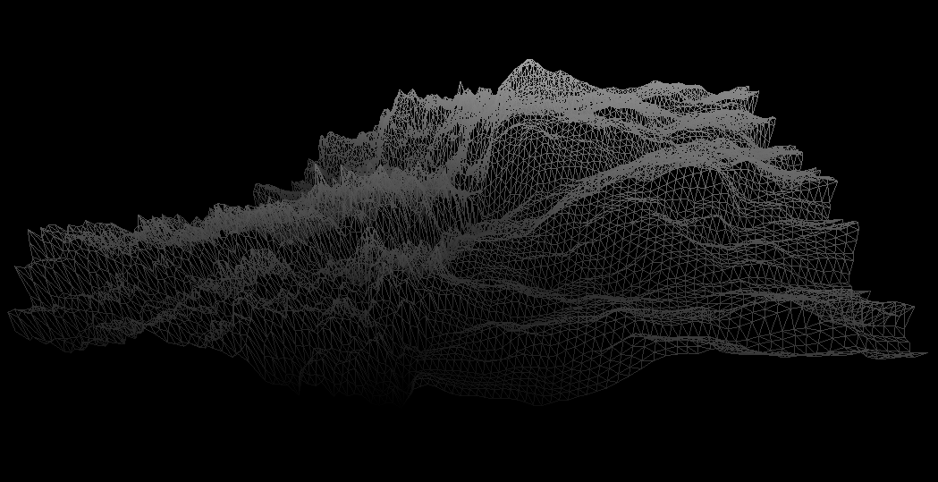
The contrast between the left and right sides (in wireframe mode), while in the left no filter was applied, in the right the values were filtered.
We can pass the filter horizontally, vertically or both.
Midpoint Displacement (or Diamond Square)
This is a more chaotic alternative to Fault Formation to simulate the geologic phenomenon known as uplift, but now instead of generating a random line, the algorithm iterates over the grid to displace a point in a height proportional to the line segment.
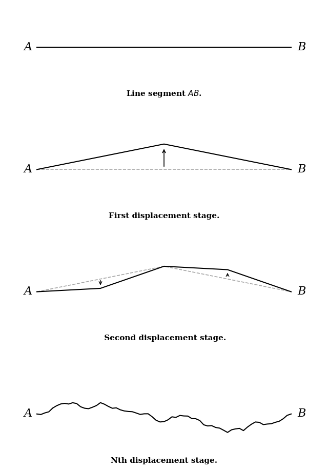
Example after multiple displacement passes.
A notable difference from Fault Formation is that Midpoint technique needs the Heightmap grid size to be a power of two. The reason for that is the way the algorithm handles its recursive iteration subdividing the grid by 2.
The algorithm is divided into 2 steps. Diamond Step which calculates each square midpoint inside the grid and Square Step which calculates each midpoint neighbours.
Diamond Step
The first step is to calculate the midpoint value based on its corner neighbours and repeat this process for each subrectangle after every iteration dividing the grid by 2 until it cannot be divided anymore.
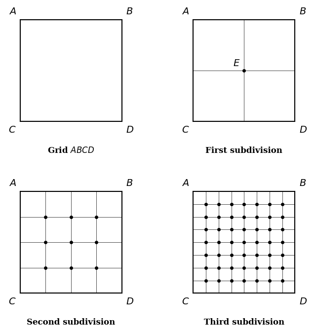
Midpoint Displacement Diamond Step
It's good to maintain a visualization of a subrectangle that is divided by 2 in each iteration while iterating over the grid to understand how it works.
To calculate the new midpoint value we take the average of the 4 corner points around it:
and add a random value proportional to the length of the line segment of the grid
we iterate over the grid and apply:
float averageVal = ((topLeft + topRight + bottomLeft + bottomRight) / 4.0f);
float finalVal   = averageVal + RandomInterval(-currentHeight, +currentHeight);
Square Step
This step should start only after the diamond step is finished for the whole grid.
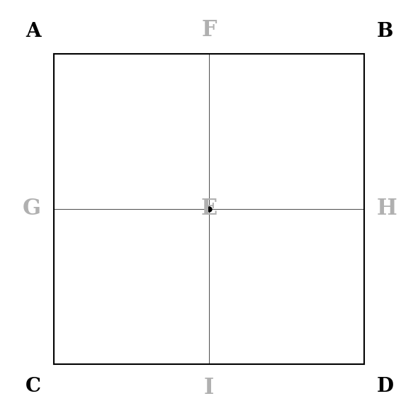
Square Step
The second step is for each iteration over the grid to calculate the heights of the midpoints of line segments (the midpoints in the image above) using the average of their 4 neighbours and again add a random value between:
We could calculate for left, right, top, down but a more elegant approach is to just calculate left and top to avoid changing the height values multiple times while iterating over the same points.
float currLeftMid = (currTopLeft + currCenter + currBotLeft + prevXCenter) / 4.0f + RandomInterval(-currentHeight, +currentHeight);
float currTopMid  = (currTopLeft + currCenter + currTopRight + prevYCenter) / 4.0f + RandomInterval(-currentHeight, +currentHeight);
After each iteration of Diamond Step and Square Step we divide the current iteration subrectangle by 2 and multiply the height by a value between 0 and 1.
Where
- Height
- Roughness constant
currentHeight *= glm::pow(2, -roughness);The value of the roughness constant will control the rate of height change.
> 1 is good to create smooth terrains.
< 1 is good to create chaotic/messy mountains.
Lastly, just like with Fault Formation, we also need to normalize our values and apply the FIR filter we implemented earlier.
Here's the result:
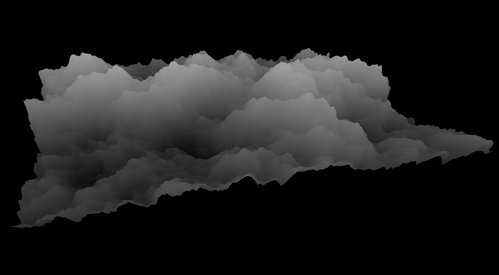
Midpoint Displacement
Conclusion
There are more algorithms to generate a terrain and advanced approaches which I might implement in the future. For now, implementing these two was important to understand the basics of how terrain generation techniques work.
The repository of this project is available below. I also added an ImGui interface so when you clone and run the project you can tweak the parameters to generate different terrains yourself.
burningbuffer/Terrain-Generator
Bye.